
Implementing Skeletal Animation
· Reading time: 11 mins
Skeletal animation is a technique that allows for fast, efficient animation of 3D models. In this post I'm going to explain the concepts and my implementation for the GPU matrix palette skinning algorithm in WebGL. Skeletal animation is quite complex and I struggled to find a guide that explained clearly what was going on, or that didn't waste too much time around language-specifics or code engineering making it quite hard to connect the dots in a simple way, so I hope I can manage to keep it simple enough.
The code and the 3D models are available for download. This time I wrote myself a custom Blender exporter in order to create a cleaner, readable JSON, but the output data layout is quite similar to Three.js's JSON format and with a little work any model can be converted.
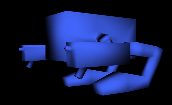
The ugly, low-poly model I designed has been inspired by Final Fantasy VII's "Custom Sweeper" enemy, and the animation I prepared features the poor guy stomping its feet, impatiently waiting for someone actually capable to keyframe a simple walk cycle. This time I'll skip the modeling part and the part related to the boilerplate code to keep it simple; if there's something you don't understand, check out my previous post or feel free to write about it in the comments.
Concepts
A skeleton, or rig, or armature, is a hierarchical structure, like a tree. In a human(oid) character, it tends to match the actual bone structure, with exceptions depending on the situation. The skeleton's nodes are called interchangeably bones or joints; I think there's a lot of confusion to be made here because the concept of bone would be better suited to describe the arcs of the graph instead. Anyway keep in mind that if you need a conceptual reference, the term "joint" is better suited to describe what the skeleton's nodes actually are.
Each joint is represented as an offset and a rotation. Extend your arm in front of you, bend the elbow and pretend your shoulder cuff is your root joint. Your shoulder will have a position and rotation with respect to an arbitrary point of reference, let's say the floor below you. Your elbow will have a displacement represented by its position relative to the shoulder (eg. we could say it's a number of centimeters horizontally away from the shoulder) and a rotation which will explain "how much" it is bent. Keep in mind that this rotation will affect only what's after it (the forearm), not what's before it; if I bend my elbow, my shoulder stays in place - exceptions to this rule should immediately be evaluated by a doctor - and my hand moves the exact same way - again see a doctor if you bend your elbow and your hand doesn't go with it. So we could say that the (joint) elbow's rotation influences the (bone) forearm's position, not the elbow in and of itself. More correctly, it influences the (joint) wrist's position since the bones don't really exist anyway.
So to sum it up:
- Root joints are defined by a position and a rotation with respect to a global reference point
- Child joints are defined with respect to their parent
- When any joint moves or rotates its children, if they exist, move and rotate by the same amount.
But what do these joints do, anyway?
Each joint is connected to zero or more vertices of a mesh in a process called weighting. More than one joint can influence the geometry of a mesh; for example, when you bend your elbow, your bicep moves a little (it contracts) while if you move your shoulder the bicep moves a lot (the whole of it moves from one point to another). The 3D artist should define which vertices are influenced, and by how much, by which bones. The bicep, for example, will be weighted, say, against the elbow by 0.1 and against the shoulder by 0.9. The weights should add up to 1, they represent the fraction of the influence exerted on the vertex. If they don't for whatever reason (approximations, choosing to restrict the influences) we should normalize them to avoid strange behaviors.
To transform a vertex, we need an affine transformation matrix which will tell us how and by how much the vertex is being transformed. This matrix is the result of the sum of all the positions and rotations of all the joints that influence the vertex. So for each vertex V:
Where Wi is the weight of V against the i-th joint, Mi is the transform matrix of the joint and n the number of joints.
Calculating the matrices
Calculating the matrices during an animation is not really a piece of cake. Let's go in little steps.
World matrices
First of all, we should remove a layer of abstraction and express the transformations of the bones in world position. This is because at the end of the process we will want to have a matrix that tells us "move this vertex a bunch of points in this direction and rotate it by this amount", so we need to strip the information about the hierarchy from the matrices and get a matrix that gives us this information with respect only to the origin point of our world. For example, if we know that the shoulder is 1.7 m from the floor and 50cm to the left of the world's origin point, and the elbow is horizontal and 25cm away from the shoulder, we want to end up with a matrix that tells us that the elbow is 1.7m from the floor and 75cm from the world's origin point.
To do this, the algorithm is pretty simple:
for(bone in bones) {

  localMatrix = calculateMatrix(bone.rotation, bone.position)

  if(bone is root)
    bone.worldMatrix = localMatrix
  else
    bone.worldMatrix = bone.parent.worldMatrix * localMatrix
}
This works flawlessly if we make sure no children is evaluated before its parent, as brilliantly explained by Brandon Jones in this post; else, we will end up with undefined parent world matrices when evaluating a child and that's not good. Annotation for later: the bone rotations should be expressed as quaternions.
Bind pose matrix
Let's consider the resting pose of our model. When the model is totally at rest, no transform is applied to the vertices; this means that the rest configuration of the skeleton should provide the shader a number of identity matrices.
But, recall, we said that each bone is specified by a position and a rotation, and we calculated these in the form of a world matrix which almost certainly won't be the identity - won't these transform our vertices even in the rest pose?
Sure they will, if we let them. To prevent this behavior, we must figure out a way to associate the bones' rest pose with the identity matrix. This simply boils down to calculating the inverse of the world matrix of each bone, so that if we multiply these two together we get the identity matrix. Let's update the algorithm like this:
for(bone in bones) {

  localMatrix = calculateMatrix(bone.rotation, bone.position)

  if(bone is root)
    bone.worldMatrix = localMatrix
  else
    bone.worldMatrix = bone.parent.worldMatrix * localMatrix

  bone.inverseBindpose = invert(bone.worldMatrix)
  bone.offsetMatrix = bone.inverseBindpose * bone.worldMatrix
}
So let's apply the transformation formula to the vertices in our rest pose (or bind pose):
becomes
But we know the Wis should add up to 1, so we get
Like we wanted, no transformations applied. We could say the inverse bindpose matrix brings each vertex in joint space, allowing then the bone's world transformation to "make sense". In fact, in the rest pose each bone transformation matrix makes sense if it doesn't move a vertex. During the animation it will make sense if it moves the vertex from the bind pose to the desired position.
Animating the skeleton
The skeletal animation will now proceed in a way conceptually similar to the keyframe animation I talked about in my last post. This time, though, we are working with transformation matrices instead of a large group of vertices. Given a time t, we can smoothly interpolate two successive keyframes whose indices correspond to the integer part of t and the same number +1, all modulo the number of keyframes, by an amount defined by the fractional part of t. For example, if we are at t = 7.32 we will interpolate the frame 7 with the frame 8 with a parameter of 0.32.
Interpolation in this case is a bit tricky though, because if you brutally lerp two matrices, glitches and imprecisions will come out. We need two separate interpolations; the first one is the simple linear interpolation between the translation vectors of the two keyframes, the second one is a spherical linear interpolation and it is necessary for correctly interpolating a quaternion-based rotation; see Wikipedia for more details.
After interpolating the vector and the quaternion, we simply build a matrix out of those two which will be the world matrix for the given bone at the point t in time.
We will store the keyframe information in our geometry with the same structure we stored the bones in; each keyframe will be an array of bones, basically.
keyframeA = keyframe[ integerPartOf(t) % #keyframes ]
keyframeB = keyframe[ integerPartOf(t) + 1 % #keyframes ]
lerpFact = fractionalPartOf(t)

boneResults = []

for(bone in bones) {

  boneA = keyframeA[ bone ]
  boneB = keyframeB[ bone ]

  translation = lerp(boneA.position, boneB.position, lerpFact)
  quaternion  = slerp(boneA.rotation, boneB.rotation, lerpFact)
  localMatrix = calculateMatrix(quaternion, translation)

  if(bone is root)
    boneResults[bone].worldMatrix = localMatrix
  else
    boneResults[bone].worldMatrix = boneResults[bone.parent].worldMatrix * localMatrix

  boneResults[bone].offsetMatrix = bone.inverseBindpose * boneResults[bone].worldMatrix
}
At the end of this, we simply use the offsetMatrix to transform our vertices.
GPU Skinning
Transforming a lot of vertices is a taxing operation for the CPU; lucky for us, it's also an extremely parallel task to do, which means we can outsource the vertex transformation to the GPU via a vertex shader, and run only a few hundreds calculations each frame to interpolate the skeleton. We will flatten the transformation matrices and upload them to the GPU via a uniform-qualified variable, because for each draw call the data will be the same; the joint indices and weights, instead, are per vertex and thus will be uploaded via an attribute.
Here's a snippet of our vertex shader. This is the function that calculates the final matrix that will have to be applied to the vertex.
uniform mat4 uBones[32];

attribute highp vec2 aSWeights;
attribute highp vec2 aSIndices;

mat4 boneTransform() {

  mat4 ret;

  // Weight normalization factor
  float normfac = 1.0 / (aSWeights.x + aSWeights.y);

  // Weight1 * Bone1 + Weight2 * Bone2
  ret = normfac * aSWeights.y * uBones[int(aSIndices.y)]
      + normfac * aSWeights.x * uBones[int(aSIndices.x)];

  return ret;
}
It is common behavior, in real time rendering, to limit the influences for a vertex to two bones, because it is extremely rare to have three or more bones influence a single vertex, and two influences is a good compromise between performances and accuracy anyway.
Conclusions
You can see a demo of the results of the algorithm here and you can download the code and the model here. The boilerplate code is not commented since it is almost identical to the one explained in my previous post, the parts inherent to skeletal animation are commented though.
I hope this article has proved useful! Again, feel free to ask for clarifications in the comments section. Till next time then!


